Renewable Recycling Robot with UR5e part 5
Algorithms to Shorten the Setup Time of Vision Guided Robots
Overview
Robotics are used a lot in enterprises for production. This enables them to produce at low cost with a constant quality. One would thus expect that given these advantages the smaller enterprises would also use robot systems. However, from the literature review it was found that the Small to Medium Enterprises are not using very much robotic systems. Usage of robotics could improve the production and help stay competitive. The problem is that current robot systems are not sufficiently flexible enough. Therefore, to be cost efficient the robot system needs to be usable for different tasks with different positions, which are usually at different places in the factory. This requires repeated reconfiguration, which is very time consuming. If this is done often it cuts the effective working time and thus increases the payback time of the robot. In conclusion, the key to increasing the uptake of robotics in is to reduce the time required for reconfiguration.
Vision systems mounted on the robot and in its surroundings can make the system a lot more flexible. If the robot for instance would be able to scan for position changes in setup and location would not be such a problem. The robot can be moved from location to another for different tasks. Or changes in the setup like different conveyor belts or machines that need to be tended could be automatically detected. If the robot could scan its new environment again and update the location this could save time.
Vision systems can also be used to determine the location of the phones that needs to be grabbed. With this the exact location of the product does not need to be programmed. This gives less constraints to environment, as it is then not necessary to design a guiding system to put a product precisely in a spot so that the robot can grab it. By using vision systems the product can be in different locations in different orientations. This makes the system a lot more flexible and possibly also more robust.
The goal of this project is to develop a industrial robot arms by automating two parts of the installation process: • Develop a system that can help with fast (extrinsic) calibration of a camera on a robot arm.The combined error should be below a 10mm level so that the camera can be used to grasp something using the camera with a Lacquey gripper. • Use the camera to automatically map the surroundings of the robot for obstacles. Mapping the surroundings (workspace) of the robot arm should be done in a safe way, during scanning the robot should not collide with an unknown object.
Implementation
The following are the key challenges
- Camera pose estimation To determine the camera location on the robot the camera location relative to a fixed point needs to be known. Therefore the first part will discuss the different camera pose estimation methods. The different implementations will be discussed, tested in simulation and with a real camera on a robot.
Implementation
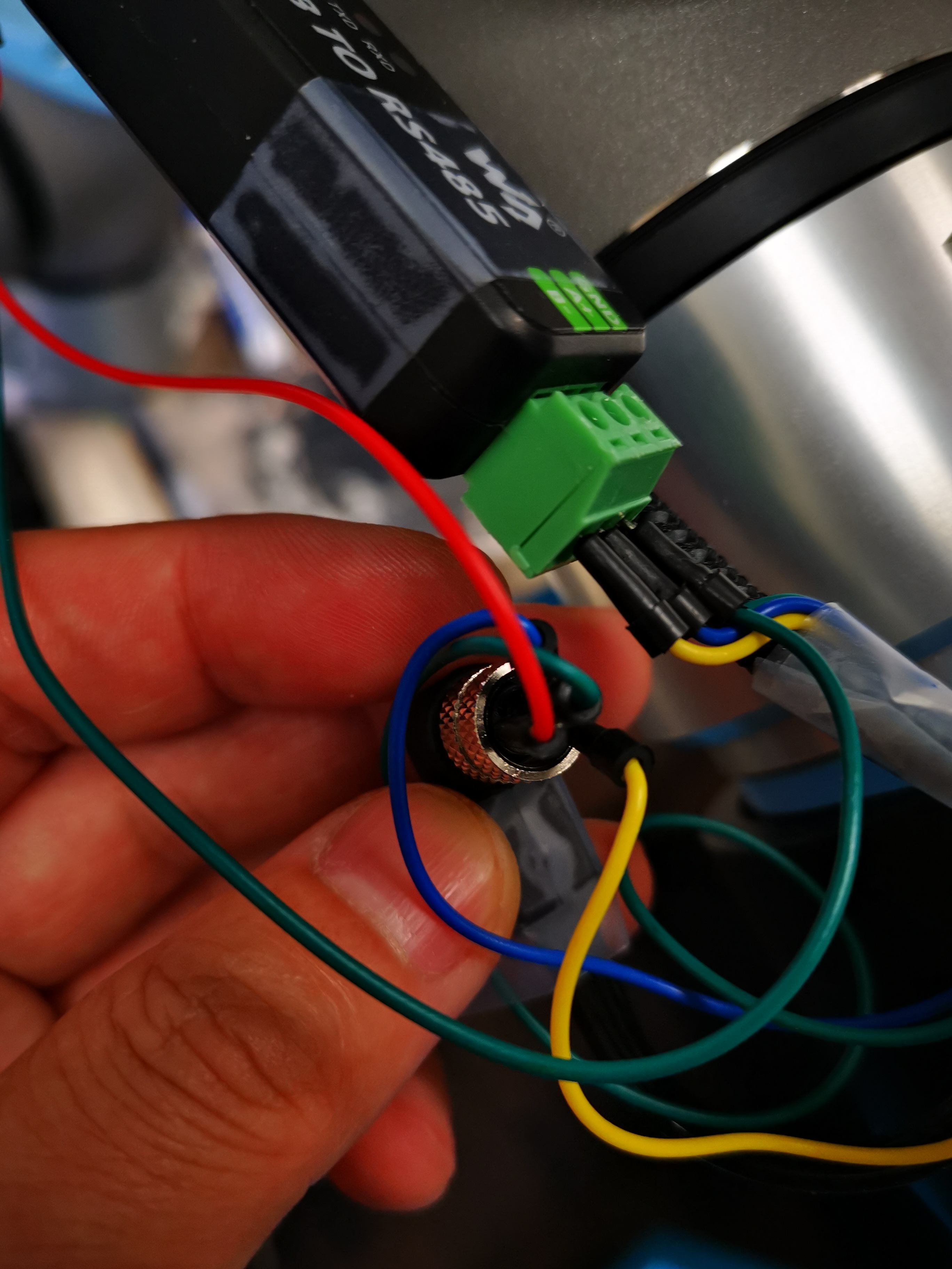
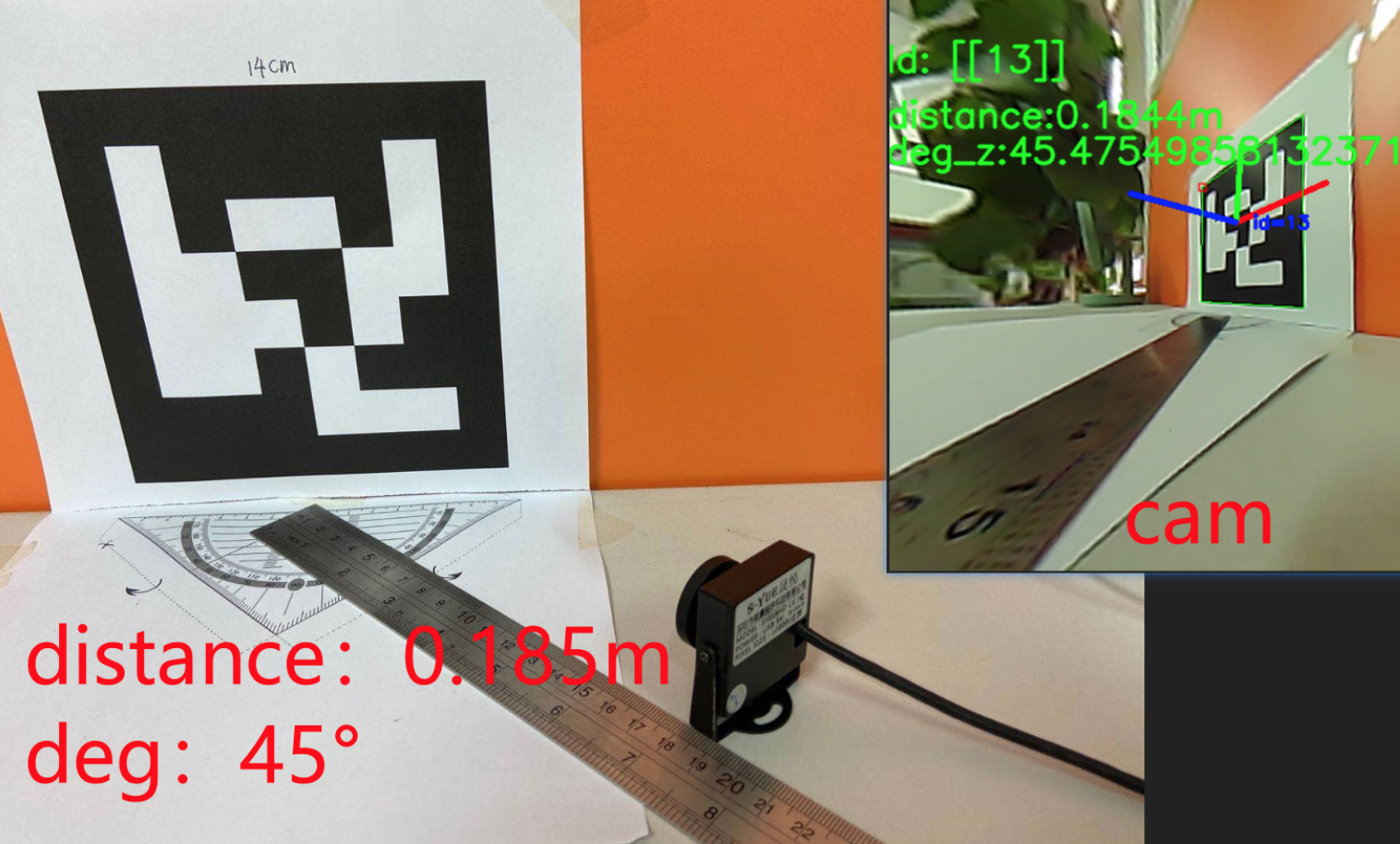
I chose to use Aruco Tag to get camera pose estimation as it is mature and widely used in industry.
I used the aruco.estimatePoseSingleMarkers() function to return the rvec rotation matrix and tvec displacement matrix of the found aurco label for conversion, find out the distance and angle of aurco relative to the camera cam, and realize the use of aurco for positioning.
Here is what looks like
The python code is
import numpy as np
import time
import cv2
import cv2.aruco as aruco
import math
#加载鱼眼镜头的yaml标定文件,检测aruco并且估算与标签之间的距离,获取偏航,俯仰,滚动

#加载相机纠正参数
cv_file = cv2.FileStorage("yuyan.yaml", cv2.FILE_STORAGE_READ)
camera_matrix = cv_file.getNode("camera_matrix").mat()
dist_matrix = cv_file.getNode("dist_coeff").mat()
cv_file.release()


#默认cam参数
# dist=np.array(([[-0.58650416 , 0.59103816, -0.00443272 , 0.00357844 ,-0.27203275]]))
# newcameramtx=np.array([[189.076828   ,  0.    ,     361.20126638]
#  ,[  0 ,2.01627296e+04 ,4.52759577e+02]
#  ,[0, 0, 1]])
# mtx=np.array([[398.12724231  , 0.      ,   304.35638757],
#  [  0.       ,  345.38259888, 282.49861858],
#  [  0.,           0.,           1.        ]])


cap = cv2.VideoCapture(0)
# cap.set(cv2.CAP_PROP_FOURCC, cv2.VideoWriter_fourcc('M', 'J', 'P', 'G'))
# cap.set(cv2.CAP_PROP_FRAME_WIDTH, 1920)
# cap.set(cv2.CAP_PROP_FRAME_HEIGHT, 1080)

font = cv2.FONT_HERSHEY_SIMPLEX #font for displaying text (below)

#num = 0
while True:
    ret, frame = cap.read()
    h1, w1 = frame.shape[:2]
    # 读取摄像头画面
    # 纠正畸变
    newcameramtx, roi = cv2.getOptimalNewCameraMatrix(camera_matrix, dist_matrix, (h1, w1), 0, (h1, w1))
    dst1 = cv2.undistort(frame, camera_matrix, dist_matrix, None, newcameramtx)
    x, y, w1, h1 = roi
    dst1 = dst1[y:y + h1, x:x + w1]
    frame=dst1

    #灰度化,检测aruco标签,所用字典为6×6----250
    gray = cv2.cvtColor(frame, cv2.COLOR_BGR2GRAY)
    aruco_dict = aruco.Dictionary_get(aruco.DICT_6X6_250)
    parameters =  aruco.DetectorParameters_create()

    #使用aruco.detectMarkers()函数可以检测到marker,返回ID和标志板的4个角点坐标
    corners, ids, rejectedImgPoints = aruco.detectMarkers(gray,aruco_dict,parameters=parameters)

#    如果找不打id
    if ids is not None:
        #获取aruco返回的rvec旋转矩阵、tvec位移矩阵
        rvec, tvec, _ = aruco.estimatePoseSingleMarkers(corners, 0.05, camera_matrix, dist_matrix)
        # 估计每个标记的姿态并返回值rvet和tvec ---不同
        #rvec为旋转矩阵,tvec为位移矩阵
        # from camera coeficcients
        (rvec-tvec).any() # get rid of that nasty numpy value array error
        #print(rvec)


        #在画面上 标注auruco标签的各轴
        for i in range(rvec.shape[0]):
            aruco.drawAxis(frame, camera_matrix, dist_matrix, rvec[i, :, :], tvec[i, :, :], 0.03)
            aruco.drawDetectedMarkers(frame, corners,ids)


        ###### 显示id标记 #####
        cv2.putText(frame, "Id: " + str(ids), (0,64), font, 1, (0,255,0),2,cv2.LINE_AA)


        ###### 角度估计 #####
        #print(rvec)
        #考虑Z轴(蓝色)的角度
        #本来正确的计算方式如下,但是由于蜜汁相机标定的问题,实测偏航角度能最大达到104°所以现在×90/104这个系数作为最终角度
        deg=rvec[0][0][2]/math.pi*180
        #deg=rvec[0][0][2]/math.pi*180*90/104
        # 旋转矩阵到欧拉角
        R=np.zeros((3,3),dtype=np.float64)
        cv2.Rodrigues(rvec,R)
        sy=math.sqrt(R[0,0] * R[0,0] +  R[1,0] * R[1,0])
        singular=sy< 1e-6
        if not singular:#偏航,俯仰,滚动
            x = math.atan2(R[2, 1], R[2, 2])
            y = math.atan2(-R[2, 0], sy)
            z = math.atan2(R[1, 0], R[0, 0])
        else:
            x = math.atan2(-R[1, 2], R[1, 1])
            y = math.atan2(-R[2, 0], sy)
            z = 0
        # 偏航,俯仰,滚动换成角度
        rx = x * 180.0 / 3.141592653589793
        ry = y * 180.0 / 3.141592653589793
        rz = z * 180.0 / 3.141592653589793

        cv2.putText(frame,'deg_z:'+str(ry)+str('deg'),(0, 140), font, 1, (0, 255, 0), 2,
                    cv2.LINE_AA)
        #print("偏航,俯仰,滚动",rx,ry,rz)


        ###### 距离估计 #####
        distance = ((tvec[0][0][2] + 0.02) * 0.0254) * 100  # 单位是米
        #distance = (tvec[0][0][2]) * 100  # 单位是米


        # 显示距离
        cv2.putText(frame, 'distance:' + str(round(distance, 4)) + str('m'), (0, 110), font, 1, (0, 255, 0), 2,
                    cv2.LINE_AA)

        ####真实坐标换算####(to do)
        # print('rvec:',rvec,'tvec:',tvec)
        # # new_tvec=np.array([[-0.01361995],[-0.01003278],[0.62165339]])
        # # 将相机坐标转换为真实坐标
        # r_matrix, d = cv2.Rodrigues(rvec)
        # r_matrix = -np.linalg.inv(r_matrix)  # 相机旋转矩阵
        # c_matrix = np.dot(r_matrix, tvec)  # 相机位置矩阵

    else:
        ##### DRAW "NO IDS" #####
        cv2.putText(frame, "No Ids", (0,64), font, 1, (0,255,0),2,cv2.LINE_AA)


    # 显示结果画面
    cv2.imshow("frame",frame)

    key = cv2.waitKey(1)

    if key == 27:         # 按esc键退出
        print('esc break...')
        cap.release()
        cv2.destroyAllWindows()
        break

    if key == ord(' '):   # 按空格键保存
#        num = num + 1
#        filename = "frames_%s.jpg" % num  # 保存一张图像
        filename = str(time.time())[:10] + ".jpg"
        cv2.imwrite(filename, frame)
- Extrinsic calibration To combine with the pose of the robot to get an estimate of the location of the camera on the robot. This will be tested in simulation and on a real robot arm. As the relative location of UR5-e and the test station can be moved for some reason the calibration needs to be done continuously to get most accurate location.
- Workspace Mapping The last part discusses the methods that can be used to get a 3D map of the obstacles in the direct environment of the robot
Video Links
UR-5e Dual gripper control

Python, Java, ML